Read the manual thoroughly and understand all of the instructions, cautions, and warnings before using this equipment. If any section of the manual is not understood, contact your nearest authorized dealer, or contact Generac Customer Service at 1-888-436-3722 (1-888-GENERAC), or www.generac.com with any questions or concerns.
Control panel wiring for home standby generators
Control wires allow for proper communication and functionality between the generator, transfer switch, and utility power source. In a Generac Home Standby Generator installation, several key control wires must be properly connected and functioning for optimal performance.
Environment
This article applies to Generac Guardian series and Next Generation series air-cooled home standby generators.
Note: The information in this article comes from the installation manuals for each respective generator series. Installation manuals can be found using the product information & user manual lookup on Generac.com.
Section guide
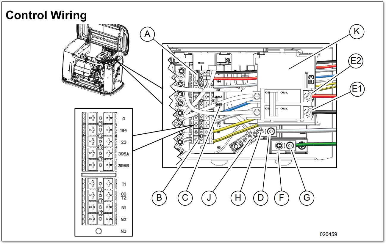
Electrical wiring connection points
| ID | Description | ID | Description | ID | Description |
|---|
| A | Control wire terminal block | E1 | Power lug E1 | H | Neutral stud |
| B | Sense wire terminal block | E2 | Power lug E2 | J | Neutral bar |
| C | Terminal block jumper | F | Ground stud | K | Customer connection block |
| D | Neutral lug | G | Equipment ground lug |
Generator wiring
| Wire color | Wire numbers |
|---|
| YELLOW | N1 & N2 - 240 VAC - Sensing for utility dropout and pickup |
| BLUE * | T1 - Fused 120 VAC for battery charger |
| WHITE * | 00/T2 - Neutral for battery charger |
| BLACK ** | 0 - DC (-) Common ground wire |
| RED | 194 - DC (+) 12 VDC for transfer controls |
| WHITE | 23 - Transfer control signal wire |
*Must be connected to keep the battery charged whether the unit is running or not
**Required if the generator is paired with optional Digital Power Management (DPM) smart technology
| ID | Description | ID | Description | ID | Description | ID | Description |
| A | DC Terminal Block | C2 | Wire tie for control wire | E2 | Power lug E2 | H | Neutral stud |
| B | AC Terminal Block | D | Neutral lug | F | Ground stud | J | Neutral bar |
| C1 | Wire tie for sense wires | E1 | Power lug E1 | G | Ground lug | — | — |
N1/N2 – Utility Voltage Sensing Wires (240V)
The N1 and N2 wires are responsible for sensing utility power dropout and pickup. These wires originate in the switch and must have 120VAC each (240VAC between them). The N1/N2 fuses in the Automatic Transfer Switch (ATS) protect these terminals. If the generator starts even when utility power is present, check this connection and fuses.
T1 – Battery Charge Circuit (120V)
The T1 wire powers the generator's battery charger and originates in the switch. It provides the 120VAC required to operate the internal battery charger. The T1 fuse in the ATS protects this circuit. If the generator batteries keep dying, check this connection and fuse.
00 Neutral (White)
A designated wire for neutral per NEC 2023 code. This wire is included on all new generators manufactured in and after 2023. If this connection is present on the generator, then this wire must be connected for a battery charger to work.
23/194 – Transfer Circuit
Wire 194 provides 12VDC to the ISACM board at the transfer switch. This voltage is used for powering the control board as well as the transfer relay. Wire 23 provides a ground for the transfer relay and is internally controlled by the generator's controller. If the transfer switch does not transfer, verify wire 194 has 12VDC and wire 23 has been taken to ground.
0/DC Common
The DC Common is the common ground wire and is only used with smart switches. It provides constant ground to power the Smart A/C Module (SACM). If the SACM is not operating, check this connection.
209/210 Wires – Common Alarm (Optional)
This is a customer-supplied connection that allows the generator to wire into an existing security system. These are normally open, dry contacts that close if the generator experiences a shutdown alarm. When they close, a message is sent to the home’s security system to alert it of a generator fault. These are the wires hanging loose under the control panel.
Regular maintenance, including checking these connections, is critical to ensure that the generator operates reliably when needed. If any of these connections are not functioning correctly, contact an authorized independent service dealer.