Read the manual thoroughly and understand all of the instructions, cautions, and warnings before using this equipment. If any section of the manual is not understood, contact your nearest authorized dealer, or contact Generac Customer Service at 1-888-436-3722 (1-888-GENERAC), or www.generac.com with any questions or concerns.
Manual operation of an automatic transfer switch
In some scenarios, manual operation of an automatic transfer switch is required to complete a transfer of power if electronic operation should fail.
WARNING: Do not attempt to manually run your home standby generator if it failed to start and/or shows signs of water intrusion following a storm surge event: Is it safe to run my home backup generator after a storm surge or hurricane?
Environment
This article applies to Generac home standby generators and automatic transfer switches.
DANGER: This guidance is only for service entrance rated switches that have a dead front cover. To prevent the risk of electrical shock when accessing live components, do not open or access other styles of switches: What's the Difference Between A Service-Entrance Rated and Non Service-Entrance Rated Transfer Switch?
Notes and warnings
Functional tests and adjustments
Following transfer switch installation and interconnection, inspect the entire installation carefully. A competent, qualified electrician should inspect it. The installation should comply strictly with all applicable codes, standards, and regulations. When absolutely certain the installation is proper and correct, complete a functional test of the system.
CAUTION: Equipment damage. Perform functional tests in the exact order they are presented in the manual. Failure to do so could result in equipment damage.
IMPORTANT: Before proceeding with functional tests, read and make sure all instructions and information in this section is understood. Also read the information and instructions of labels and decals affixed to the switch. Note any options or accessories that might be installed and review their operation.
DANGER: Electrocution. Do not manually transfer under load. Disconnect transfer switch from all power sources prior to manual transfer. Failure to do so will result in death, serious injury, and/or equipment damage.
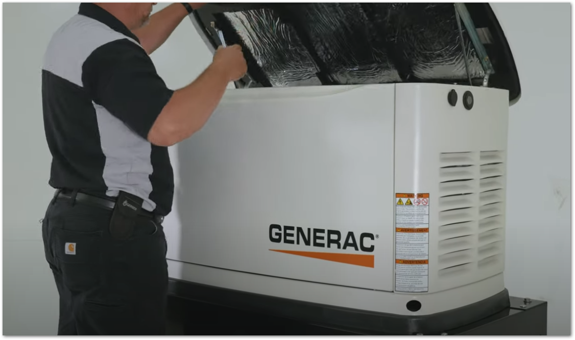
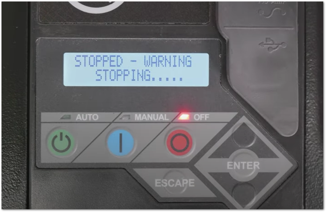
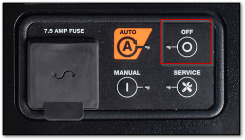
1. Open the generator lid. At the generator control panel, verify the generator is set to OFF.
Evolution series controllers
Power Zone 200 controllers
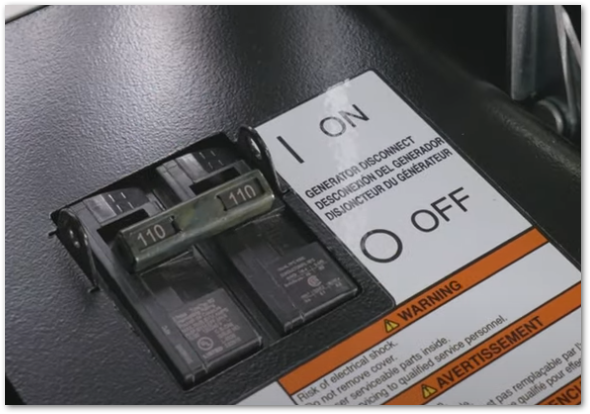
2. Set the generator main line circuit breaker (MLCB) to OFF.
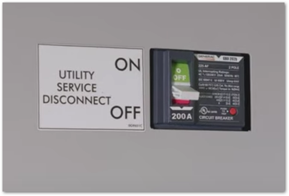
3. At the transfer switch, turn OFF the main utility service disconnect.
DANGER: Keep the dead front panel (interior protective panel) in place. Do not operate the yellow handle with the contactor exposed. Serious injury risk.
4. Observe the position of transfer mechanism main contacts (A) by observing the movable contact carrier arm. This can be viewed through the long narrow slot of the cover.
Standard orientation (most 100A and larger Generac switches)
- Handle UP. Load is connected to utility power.
- Handle DOWN. Load is connected to generator (emergency) power.
Exception: 50A Generac switches (models such as RXSW50A)
These switches use a different mechanical design and the handle positions are reversed.
Important safety note: This image is offered for reference only. Components shown in the image vary in size and orientation depending on the transfer switch model. Always refer to the transfer switch installation manual for more accurate and detailed information.
CAUTION: Equipment damage. Do not use excessive force while manually operating the transfer switch. Doing so could result in equipment damage.
Transfer to generator power source
Standard 100A and larger switches
1. Insert the yellow handle (B) into the long narrow slot of the front cover. The top of the movable contact carrier arm is yellow to be easily identified.
DANGER: Keep the dead front panel (interior protective panel) in place. Do not operate the yellow handle with the contactor exposed. Serious injury risk.
2. With the yellow handle inserted into the movable contact carrier arm slot, firmly shift the handle DOWN. Hold the handle securely, as it will move quickly after the center of travel. The transfer switch is now in the emergency (generator) position. See above for more information on the position of transfer mechanism main contacts.
3. At the generator, press the MANUAL button on the control panel to crank and start the engine.
4. Allow the engine to stabilize and warm up for a few minutes.
5. Set the generator Main Line Circuit Breaker (MLCB) to ON. Generator power is now supplying electrical loads. For more information, see What is the generator main line circuit breaker? (MLCB)
Note: Monitor the return of utility power to ensure the generator is properly shut down. Manual transfer back to utility power may be required; see the Transfer to utility power source section below for complete instructions.
50A switches (models such as RXSW50A)
1. Insert the yellow handle (B) into the long narrow slot of the front cover. The top of the movable contact carrier arm is yellow to be easily identified.
DANGER: Keep the dead front panel (interior protective panel) in place. Do not operate the yellow handle with the contactor exposed. Serious injury risk.
2. With the yellow handle inserted into the movable contact carrier arm slot, firmly shift the handle UP. Hold the handle securely, as it will move quickly after the center of travel. The transfer switch is now in the emergency (generator) position. See above for more information on the position of transfer mechanism main contacts.
3. At the generator, press the MANUAL button on the control panel to crank and start the engine.
4. Allow the engine to stabilize and warm up for a few minutes.
5. Set the generator main line circuit breaker (MLCB) to ON. Generator power is now supplying electrical loads.
Note: Monitor the return of utility power to ensure the generator is properly shut down. Manual transfer back to utility power may be required; see the Transfer to utility power source section below for complete instructions.
Transfer to utility power source
Standard 100A and larger switches
1. Set the generator MLCB to OFF.
2. Allow the generator to run and cool down for five minutes with no load applied to stabilize internal temperature.
3. Press the OFF button on the generator control panel to shut down the engine.
4. Verify that the main utility service disconnect at the transfer switch is OFF.
DANGER: Keep the dead front panel (interior protective panel) in place. Do not operate the yellow handle with the contactor exposed. Serious injury risk.
5. Insert the yellow handle (B) into the long narrow slot of the front cover. The top of the movable contact carrier arm is yellow to be easily identified.
6. With the yellow handle inserted into the movable contact carrier arm slot, firmly shift the handle UP. Hold the handle securely, as it will move quickly after the center of travel. The transfer switch is now in the utility position. See above for more information on the position of transfer mechanism main contacts.
7. Turn the main utility service disconnect at the transfer switch ON.
8. At the generator, press the AUTO button on the control panel.
9. Set the generator MLCB (generator disconnect) to ON (CLOSED).
10. Close and lock the generator lid.
50A switches (models such as RXSW50A)
1. Set the generator MLCB to OFF.
2. Allow the generator to run and cool down for five minutes with no load applied to stabilize internal temperature.
3. Press the OFF button on the generator control panel to shut down the engine.
4. Verify that the main utility service disconnect at the transfer switch is OFF.
DANGER: Keep the dead front panel (interior protective panel) in place. Do not operate the yellow handle with the contactor exposed. Serious injury risk.
5. Insert the yellow handle (B) into the long narrow slot of the front cover. The top of the movable contact carrier arm is yellow to be easily identified.
6. With the yellow handle inserted into the movable contact carrier arm slot, firmly shift the handle DOWN. Hold the handle securely, as it will move quickly after the center of travel. The transfer switch is now in the utility position. See above for more information on the position of transfer mechanism main contacts.
7. Turn the main utility service disconnect at the transfer switch ON.
8. At the generator, press the AUTO button on the control panel.
9. Set the generator MLCB (generator disconnect) to ON (CLOSED).
10. Close and lock the generator lid.
To resolve the underlying issue with power transfer, contact a Generac authorized service dealer to schedule service.


