Adjusting the engine valves
Generator owners should reference these articles before performing this procedure.
Environment
This article applies to Guardian-series generators that do not have hydraulic lifters. This article does not apply to the Next Generation Air-Cooled Standby Generator which features hydraulic lifters.
Maintenance Schedule:
Valve adjustments are listed as part of a generator's maintenance schedule. See the Where Can I Find the Maintenance Schedule for My Generac Home Standby Generator? article for more information/
Maintenance Safety:
Maintenance Kits:
Authorized Service Dealers:
Consult the User Manual:
Preparation
- Contact an an authorized service dealer for service assistance. Correct valve clearance is essential for prolonging the life of the engine. This procedure excludes units equipped with hydraulic lifters.
- Valve lash is not required on 14 or 18 kW units with 816cc engines.
- Make sure the engine is cool before checking valve clearance. Adjustment is not needed if valve clearance is within the required dimensions.
- Inspect valve clearances after the first 25 hours of operation, then after 400-hour intervals. Adjust as necessary.
Checking valve clearance
1. Close the fuel valve and disconnect the battery to avoid accidental startup.
2. Remove the spark plug wire(s) away from the spark plug(s).
3. Remove the spark plug(s).
4. Remove the four screws attaching the valve cover. Remove and discard the gasket. (Repeat for the second cylinder, if equipped.)
5. Verify the piston is at the top dead center (TDC) of its compression stroke (both valves are closed).
Note: To move the piston to TDC, remove the intake baffle at the front of the engine to access the flywheel nut. Use a large socket and socket wrench to rotate the flywheel nut clockwise, which will rotate the crankshaft. Watch the piston through the spark plug hole. The piston will move up and down Piston is at TDC when its highest point of travel.
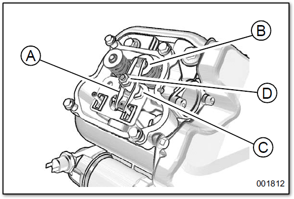
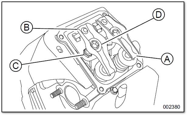
6. Reference the images below. Verify the valve clearance between each rocker arm (A) and valve stem (B) with a feeler gauge.
7. Install the replacement valve cover gasket(s).
- 10 kW - 0K8946
- 14-18 kW - 10000014827
- 20-26 kW - 0C2979
8. Install the valve cover(s). Tighten fasteners in a cross pattern, tightening to:
- 10 kW - 80 in-lbs (9.0 Nm)\
- 20-26 - 60 in-lbs (6.8 Nm)
Adjusting valve clearance
Valve lash is not required on 14 or 18 kW units with 816cc engines.
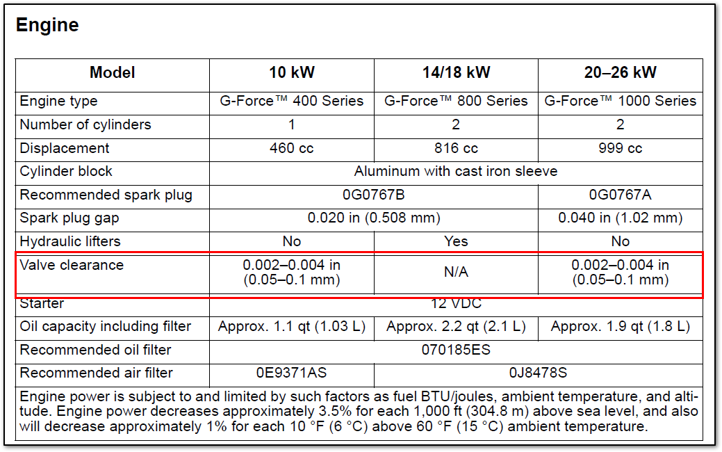
Note: The table below comes from the 10-26 kW Guardian series user manual and does not represent all Generac home standby generator models. A detailed specification sheet for a particular generator is available from a local service dealer.
Allow the engine to cool before adjusting valve clearance.
1. Remove spark plug wire(s) and position spark plug wire(s) away from spark plug(s).
2. Remove the spark plug(s).
3. Remove the four screws attaching the valve cover. Remove and discard the gasket.
4. Verify piston is at TDC of its compression stroke (both valves closed).
5. Loosen rocker jam nut (C) using a 10 mm wrench (10 kW units) or a 13 mm wrench (Guardian 20-26 kW units).
6. Turn pivot ball stud (D) using a 14 mm wrench (10 kW units), or 10 mm hex key (Guardian 20—26 kW units) while inspecting clearance between rocker arm (A) and valve stem (B) with a feeler gauge. See the table at the beginning of this section for valve clearance information.
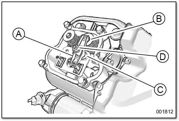
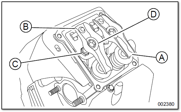
Note: Hold the rocker jam nut in place as the pivot ball stud is turned.
7. When the valve clearance is correct, hold the pivot ball stud in place with a wrench and tighten the rocker arm jam nut. Tighten the jam nut according to:
| Generator size | Jam nut torque |
|---|
| 10 kW | 53 in-lbs (6.0 Nm) |
| 20–26 kW | 174 in-lbs (19.68 Nm) |
8. Inspect the valve clearance to verify it did not change.
9. Install the new valve cover gasket.
10. Install the valve cover. Tighten the fasteners in a cross pattern. Tighten to:
| Generator size | Valve cover torque |
|---|
| 10 kW | 80 in-lbs (9.0 Nm) |
| 20–26 kW | 60 in-lbs (6.8 Nm) |
Note: Start all four screws before tightening, or it will not be possible to get all screws in place. Verify valve cover gasket is in place.
11. Install spark plug(s) and tighten to 18 ft-lbs (25 Nm).
12. Attach spark plug wire(s) to spark plug(s).
13. Repeat the process if the other cylinder is equipped.


