Read the manual thoroughly and understand all of the instructions, cautions, and warnings before using this equipment. If any section of the manual is not understood, contact your nearest authorized dealer, or contact Generac Customer Service at 1-888-436-3722 (1-888-GENERAC), or www.generac.com with any questions or concerns.
4G/LTE device installation
Owners of compatible Generac Home Standby generators can have the Mobile Link 4G LTE device installed to connect the generator to Verizon's cellular network to deliver generator information to the Mobile Link app. This allows users to remotely monitor their generator. This device can also be swapped on generators with an existing Mobile Link Wi-Fi device. See What are the available Mobile Link subscription plans? for more information.
Discontinued Notice: The 4G/LTE aftermarket accessory has been discontinued. Upgrading to the Connectivity Cellular Accessory is recommended for users who wish to add connectivity to their generator or users experiencing ongoing connectivity issues. It is compatible with more generators and uses multiple carrier networks to offer greater coverage. Basic (free) and Premium cellular plans are available for users of this device. See here to upgrade: Connectivity Cellular Accessory.
Environment
Mobile Link 4G/LTE device: This article applies to the installation of the Mobile Link 4G/LTE aftermarket connectivity device. If you need instructions for installing the newer Cellular Connectivity Accessory, see here: How to install the Mobile Link Generac Connectivity Cellular Accessory
Note: To determine which Mobile Link device you have, see here: Mobile Link Wi-Fi, Cellular, and LTE device compatibility guide.
Guardian-series generators: This article applies to Guardian series air-cooled hope standby generators.
Discontinued Notice: The 4G/LTE aftermarket accessory has been discontinued. Upgrading to the Connectivity Cellular Accessory is recommended for users who wish to add connectivity to their generator or users experiencing ongoing connectivity issues. It is compatible with more generators and uses multiple carrier networks to offer greater coverage. Basic (free) and Premium cellular plans are available for users of this device. See here to upgrade: Connectivity Cellular Accessory.
How can I check if my generator supports this device?
Verify your generator's controller is compatible with the 4G/LTE device. See: Mobile Link Wi-Fi, Cellular, and LTE device compatibility guide.
Will I have coverage?
The Mobile Link 4G/LTE Device uses Verizon's cellular network to establish a connection. Service availability can be estimated using the coverage map on Verizon.com.
If reliable Verizon cell coverage is unavailable in your area, contact your local service dealer about upgrading to the Connectivity Cellular Device, which uses multiple carrier networks.
Where can I purchase a Mobile Link Connectivity Device?
For up-to-date information on currently available Mobile Link connectivity devices, see Mobile Link Wi-Fi, Cellular, and LTE device compatibility guide.
Can I install this myself?
For safety reasons, the manufacturer requires that this equipment be initially installed by an Independent Authorized Service Dealer (IASD) or other qualified electrician or installation technician who is familiar with applicable codes, standards, and regulations. This installation generally requires the simple replacement of the assembly with a new unit, which can typically be performed by the generator owner.
If an end user is not comfortable installing the device, they can contact their local dealer to schedule a service visit.
This article will include:
Verify operation of the generator
Verify the generator is operating and performing properly before installing the Mobile Link 4G LTE device on the generator.
Prepare the generator
Disable Wi-Fi
Generators with the Evolution 2.0 controller are equipped with a Wi-Fi module on the rear panel. Wi-Fi functionality (if enabled) must be disabled before installing a Mobile Link cellular unit. Proceed as follows to disable Wi-Fi:
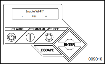
1. Open the generator's lid. Press OFF and then ESCAPE to access the control panel's main menu.
2. Use the up and down arrows near the ENTER button to select WIFI and press ENTER.

Note: If the display reads WiFi Setup?, this indicates the generator is equipped with Wi-Fi, but functionality it is already disabled. Skip step 2, simply prrsss ENTER to return to the READY TO RUN status.
3. Use the arrow keys to toggle between Yes and No. Select No and press ENTER.
4. After disabling Wi-Fi, the control panel will prompt the user to SELECT HOUR (0-23). Use the up and down arrows and ENTER buttons to set the current time and date in military time.
5. Press ESCAPE to return to the default controller display.
Set the generator's Main Line Circuit Breaker to OFF (OPEN)
Depending on the generator model, the main circuit breaker is located either in an external breaker box (A), or internally near the controller (B).

1. Turn the Mail Line Circuit Breaker to OFF (OPEN).
Note: With the Main Line Circuit Breaker in the OFF (CLOSED) position, the generator will be unable to send power to the house. This step is required as a safety measure during the following installation process. It will need to be returned to the ON position at the end of the installation in order for the generator to function properly during an outage.
Install the Mobile Link 4G LTE device
Prepare the generator (new installations)
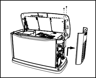
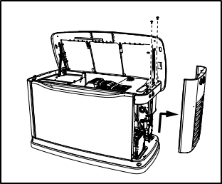
1. Unlock both locks, open the generator lid, and remove the front panel.
2. If the generator is equipped with an internal breaker near the controller, remove the end panel from the right side. Otherwise, the side panel will be removed during a later step. Proceed to Step 3.
3. Turn the generator OFF. Remove the 7.5 amp fuse from the generator control panel.
Note: There are different control panel configurations for various model years.
4. Turn the main utility disconnect breaker in the home’s electrical panel to OFF or OPEN.
Note: With the main utility disconnect breaker in the home's electrical panel set to OFF (OPEN), the 120V T1 terminal mentioned in the following step should no longer be energized. This step is required as a safety measure during the following installation process.
5. Using an appropriate fuse puller, remove the T1 fuse from the transfer switch.
6. Disconnect the negative (–) battery cable, then the positive (+) battery cable.
7. If the generator is equipped with an external breaker box, remove the controller's sheet metal cover and fasteners.
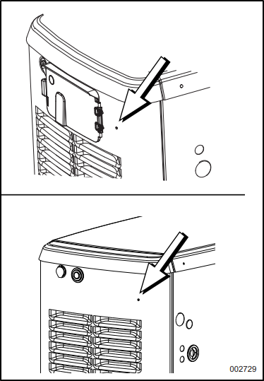
Note: 2013 and later models have a pre-positioned dimple on the end panel. The dimple marks the center of the mounting hole to be drilled.
9. Inspect the area behind the external breaker box to verify all wires are moved out of the way to prevent damage during drilling.
Note: Models equipped with an internal breaker mounted near the controller will already have the end panel removed at this point. Carefully place the end panel face up on a clean, smooth, flat surface to avoid damaging the paint.
10. Drill a 1-1/8 in (29 mm) diameter hole with the dimple as the center point.
11. Proceed to the Connecting the Mobile Link Unit section.
Prepare the generator (Equipped with an Existing Mobile Link connectivity device)
1. Unlock both locks, open the generator lid, and remove the front panel.
2. If the generator is equipped with an internal breaker near the controller, remove the end panel from the right side. Otherwise, the panel should have already been removed in a previous step; proceed to Step 3.
3. Turn the generator OFF. Remove the 7.5 amp fuse from the generator control panel.
Note: There are different controller configurations for various model years.
4. Set the main utility disconnect breaker in the home’s electrical panel to OFF (OPEN).
Note: With the main utility disconnect breaker in the home's electrical panel set to OFF (OPEN), the 120V T1 terminal mentioned in the following step should no longer be energized. This step is required as a safety measure during the following installation process.
Warning: Generac does NOT recommend end users attempt to modify or service internal generator wiring or attempt to service the transfer switch: How Can I Find a Generac Service Dealer in My Area?
5. Using an appropriate fuse puller, remove the T1 fuse from the transfer switch.
Note: With the main utility disconnect breaker in the home's electrical panel set to OFF (OPEN), the 120V T1 terminal should no longer be energized. This step is required as a safety measure during the following installation process.
6. Disconnect the negative (–) battery cable, then the positive (+) battery cable.
7. Disconnect the wire harness from port 1 on the controller.
Connect the new Mobile Link 4G LTE device
1. Connect the leads to the positive and negative battery terminals.
2. Push the six-pin connector through the supplied plastic fitting (A).
3. Place the green gasket (B) on the threaded end of the plastic fitting. Push the threaded end through the controller end panel.
4. Thread the antenna (C) into the Mobile Link cellular unit (D). Rotate the antenna clockwise until it is secure. Position the antenna pointing up.
Note: Do not overtighten the antenna; hand-tighten only.
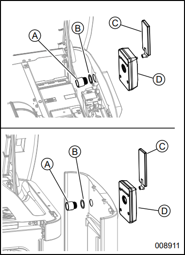
5. Insert the six-pin harness connector from the Mobile Link cellular unit into the mating connector of the wiring harness. The connector will only fit one way. DO NOT force it into place.
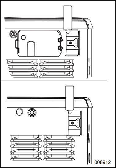
6. With the connector installed, tighten the plastic fitting to secure the Mobile Link cellular unit until it is tight and the device is secured to the end panel. Align the antenna vertically, and verify the Mobile Link logo is on the left side. The device should now be physically mounted on the side of the generator. See picture below.
Note: Hold the Mobile Link cellular device firmly and tighten the nut during installation to avoid damage to the wiring harness.
Connect the wiring harness
1. Locate the accessory port. The accessory port is an eight-pin connector on the underside of the controller. On models equipped with an external breaker box, lift the controller to gain access to the accessory plug location. On models equipped with an internal breaker mounted near the controller, the accessory port is visible from the battery compartment when the end panel is removed (see the image below).
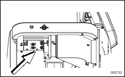
Note: The accessory port is located on the underside of the control panel, directly above the battery. If there is a decal labeled “Port 1” or “Accessory Prt 1,” remove the decal to locate the port.
2. Install the eight-pin connector harness into accessory port 1 on the controller.
Note: The connector will only fit one way. DO NOT force.
3. Connect the battery cables. Connect the positive battery cable first, then connect the negative battery cable.
For units equipped with Evolution 1.0 controllers or earlier: See the image below. Loosen and remove the nuts (A) from both positive (+) and negative (–) battery terminal screws on the battery cables. Slide the harness power wires (B) over the battery terminal screws and replace the nuts. Tighten securely.
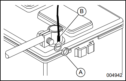
Note: Harness power wires consist of a black negative (-) wire and a fused red positive (+) wire.
Complete the installation of the 4G LTE device
1. Install the generator end panel, controller, or sheet metal controller cover. Install and tighten the retaining fasteners.
2. Verify the generator is OFF.
3. Install the generator controller fuse.
4. Install the T1 fuse into the transfer switch using an appropriate fuse puller.
5. Turn the main breaker in the home electrical panel to ON. On the generator control panel, follow the installation wizard and validate the correct date, time, etc.
6. Place the generator into AUTO.
7. Set the Mail Line Circuit Breaker to ON (CLOSED). This needs to be left in the ON position in order for the generator to sent power to the home during the next outage.
Note: All of these steps are required for the generator to run in automatic mode and properly power the home during an outage. The generator will not send power to the home unless the generator's Main Line Circuit Breaker is in the ON (CLOSED) position.
Mobile Link cellular LEDs
See: What Do the Lights on the Front of the Mobile Link Cellular LTE Accessory Mean?
Finish Mobile Link setup
How do I change the Mobile Link device in my Mobile Link account?
If you recently installed a replacement Mobile Link device on your generator and need to add it to your Mobile Link account, contact your preferred Generac dealer or Mobile Link Support (855-436-8439) with the device serial number and generator serial number. Your dealer or Mobile Link Support will then update the device in your Mobile Link account.